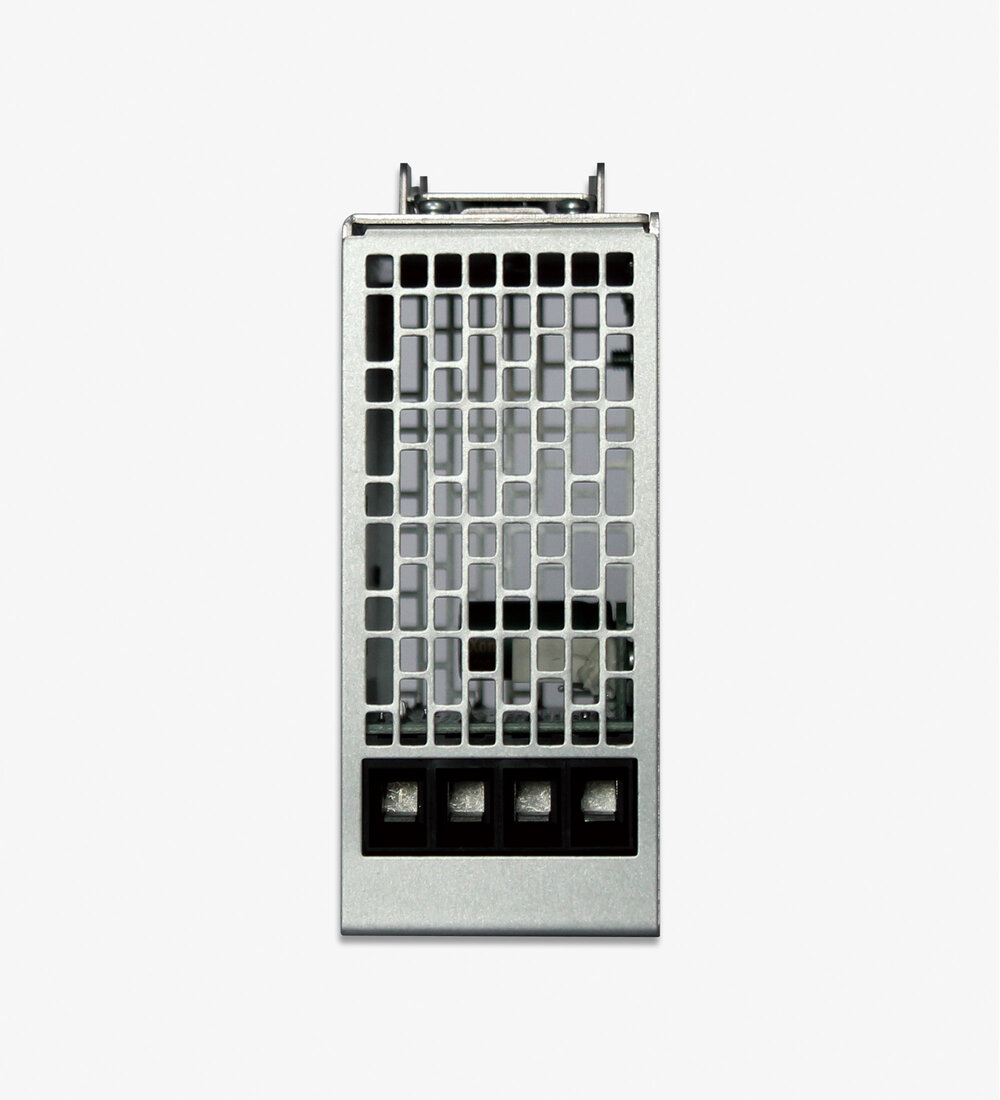
DIN Rail Redundancy Module 9 - 60 V DC/ 2 x 40 A Input - 40 A Output
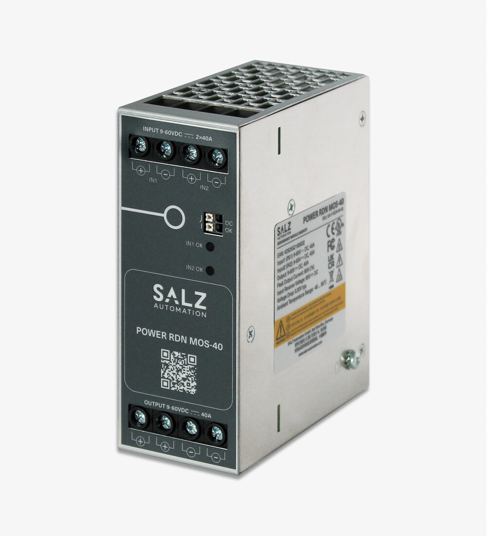
POWER RDN MOS-40
DIN Rail Redundancy Module with MOSFET technology for 9–60 VDC, 2x 40 A inputs, ultra‑low voltage drop and N+1 redundancy.
FunctionDIN Rail MOSFET Module 9 - 60 V DC/ 2 x 40 A Input - 40 A Output, N+1 redundancy,DC OK monitoring.
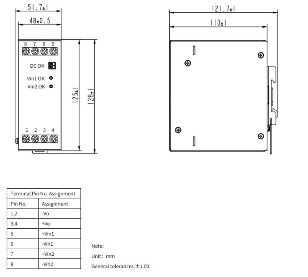
Features- Ultra Slim Dimensions
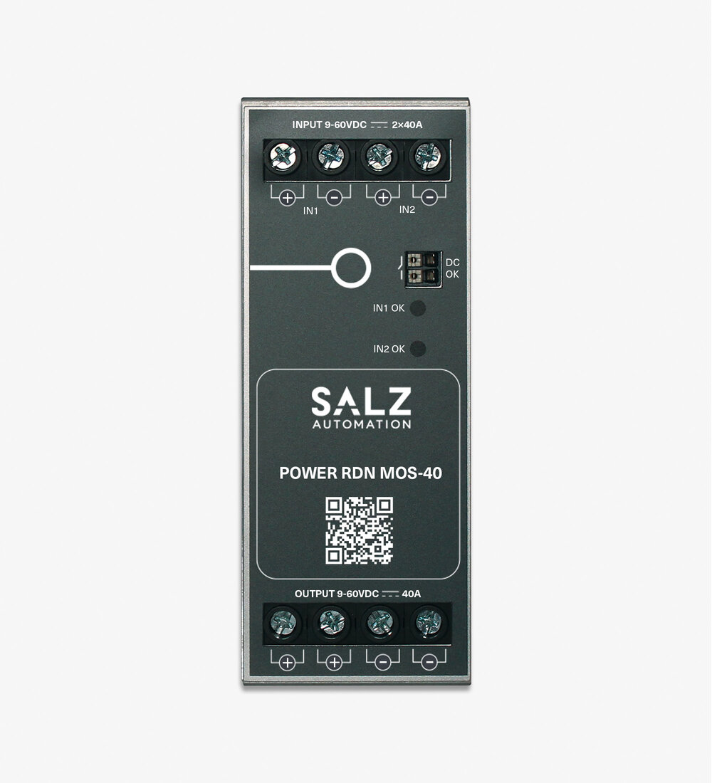
- DC OK LED
- Input Voltage Balance OK LED


Additional Information
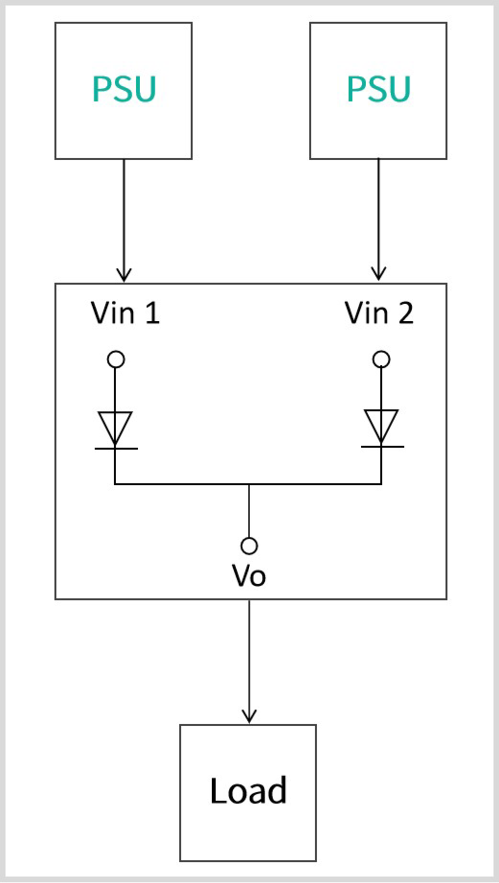
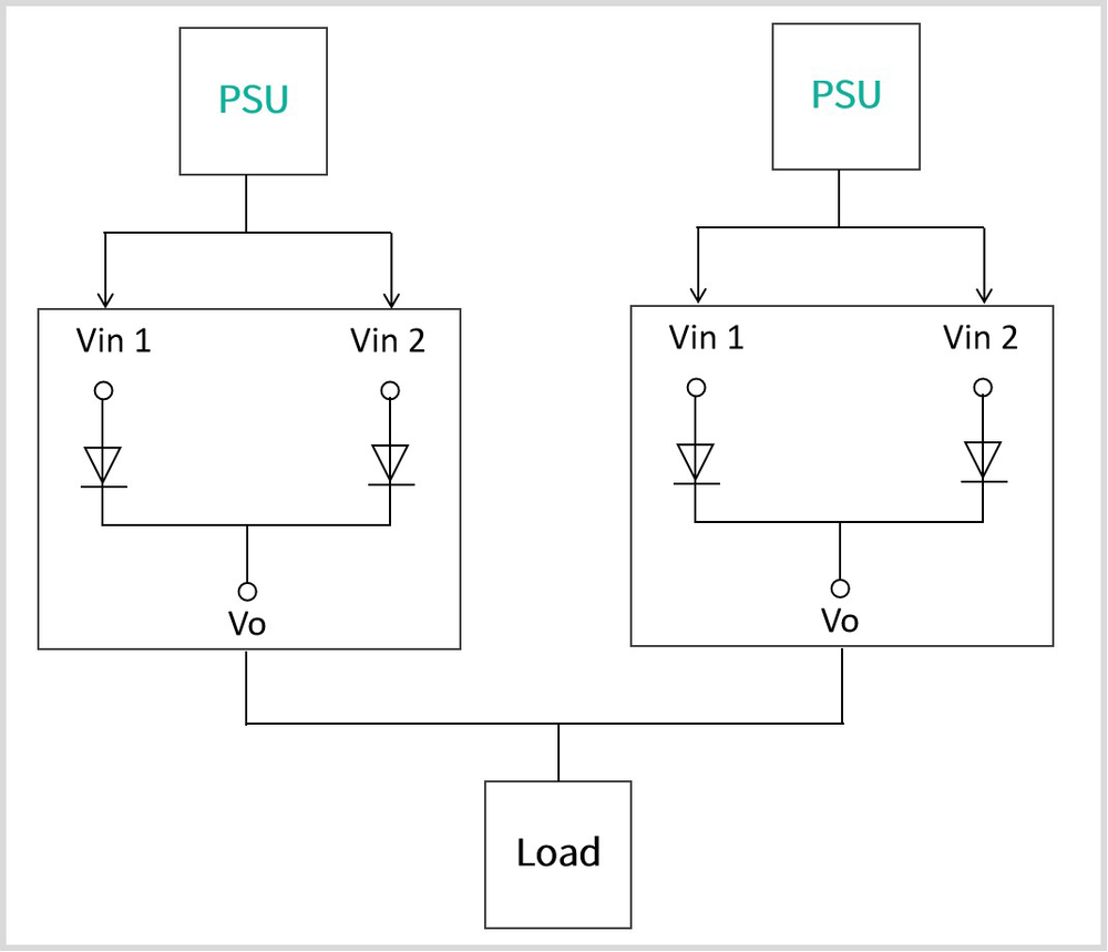
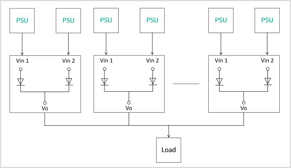
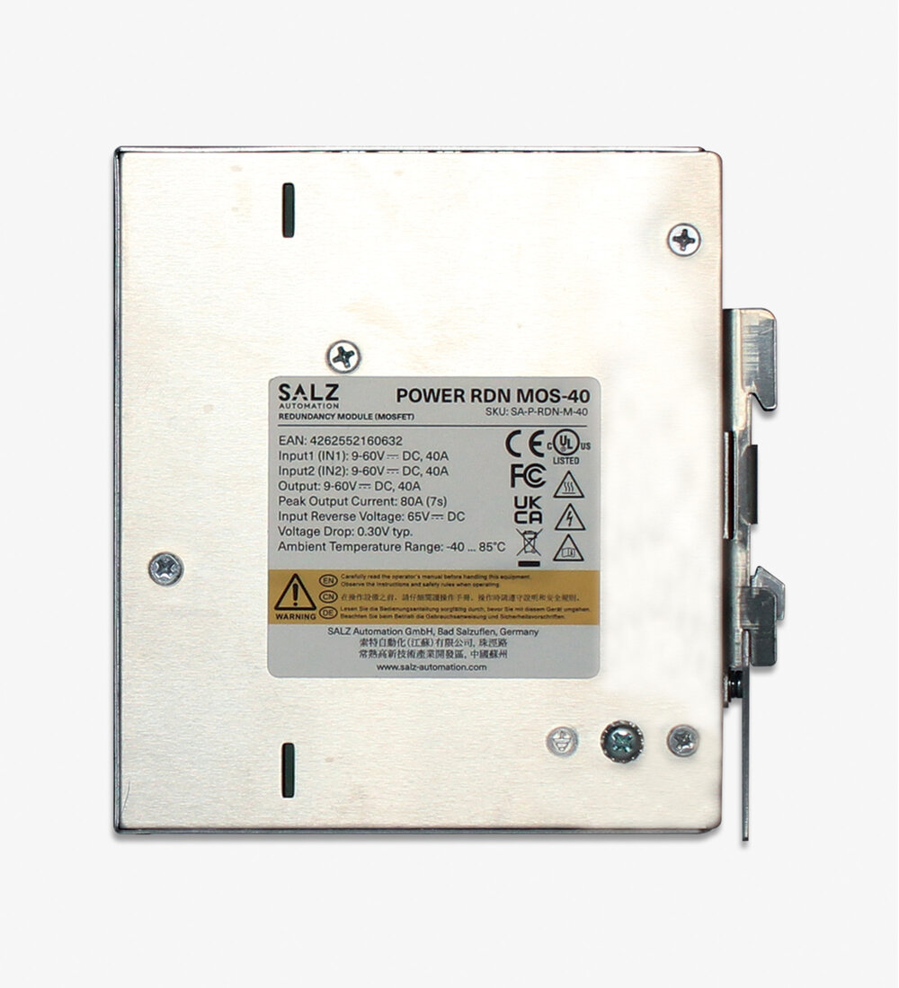
The POWER RDN MOS-40 represents advanced redundancy technology utilizing high-efficiency MOSFET switching for superior power distribution performance in demanding industrial applications. With MOSFET-based redundancy architecture, this module achieves an ultra-low voltage drop of just 0.30V typical, maximizing system efficiency while delivering robust 40A dual-channel redundancy protection.
Key Technical Features:
-
Wide Input/Output Range: 9-60 VDC operation supporting 12V, 24V, and 48V nominal voltages
-
MOSFET-Based Redundancy: High-efficiency MOSFET technology with ultra-low voltage drop of 0.30V (Vin-Vout) - more than 50% lower than diode-based solutions
-
High Current Capacity: 40A rated current per input channel with 80A peak current capability (7 seconds)
-
Advanced Monitoring: Built-in 2-channel LED DC OK indicators and relay alarm contact for comprehensive system diagnostics
-
Superior Protection: Overload and short circuit protection up to 80A for 7 seconds without damage
-
Industrial Reliability: Enhanced conformal coating, 65 VDC reverse voltage protection, and Class I safety rating
-
Optimized Design: DIN rail mounting with natural convection cooling
Applications: Perfect for high-power industrial automation, heavy machinery control, robotics systems, energy management, telecommunications infrastructure, and demanding applications where maximum efficiency and high current capacity are critical requirements.
Statement:
- Redundancy Modules should be considered as a part of the system components, and electromagnetic compatibility needs to be checked in conjunction with the terminal equipment.
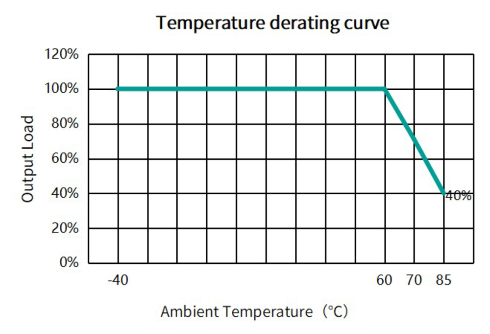
- When working at an altitude of over 2000 meters, please derate 5% per KM.
- Installation distance: Recommended top 40mm, bottom 20mm, left and right 5mm. If adjacent devices are heating up, lateral distance of 5 mm.
- The case needs to be connected to ground of system when terminal equipment in operating.
- All indicators in this guidebook are tested according to our company's standards.

Ultra Slim Dimensions
To save space in your control cabinet, our power supplies are designed to reduce size.

DC OK LED
If output voltage is decreasing the DC OK LED turns off. In "normal" output voltage condition the LED is on.

Input Voltage Balance OK LED
LED Indication to signaling the input voltage balance is OK.